Let’s take another look at our circuit and add a useful component that will allow us to quickly and easily control the value of our goal coordinate for our project: a joystick! We can use the up-down axis of the joystick to increase and decrease the value of our y variable, which moves our robot up and down, and use the left-right axis of the joystick to increase and decrease the value of our x variable, moving our robot from left to right.
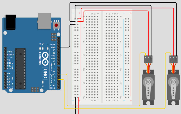
Connect the positive voltage pin of the joystick to the 5V pin on the Arduino, through the power rails of the breadboard. Connect the GND pin to the GND rail of the breadboard, and the x and y pins of the joystick to the A0 and A1 pins on the Arduino.

Now that we have wired all the components we’ll need, the final step will be converting our inverse kinematics equations into code and adding in the few lines we need to read our joystick values! Thankfully, Arduinos are great at math and have functions for each of the mathematical operations we’ll need to complete the calculations built into the programming language.
#include "Servo.h"
Servo servoOne;
Servo servoTwo;
//Setting up our IK variables
double x = 30.0;
double y = 120.0;
double linkOne = 100.0;
double linkTwo = 100.0;
double alphaOne;
double alphaTwo;
double alphaFinal;
double betaOne;
double betaTwo;
double betaFinal;
double c;
double d = 60.0;
double e;
int xval;
int yval;

void setup() {
  Serial.begin(9600);
  servoOne.attach(3);
  servoTwo.attach(5);
}

void loop()
{
  //IK Calculations
  yval = analogRead(A0);
  xval = analogRead(A1);
  c = sqrt((x*x)+(y*y));
  e = sqrt(((d-x)*(d-x))+(y*y));
  alphaOne = atan(y/x) * (180/PI);
  alphaTwo = acos(((linkTwo*linkTwo)-(c*c)-(linkOne*linkOne))
            /(-2*linkOne*c)) * (180/PI);
  betaOne = atan(y/(d-x)) * (180/PI);
  betaTwo = acos(((linkTwo*linkTwo)-(e*e)-(linkOne*linkOne))
            /(-2*linkOne*e)) * (180/PI);
  if(x < 0){ alphaFinal = 180 + ((alphaOne) + (alphaTwo)); betaFinal = 180 - ((betaOne) + (betaTwo)); } else if(x > d){
      alphaFinal = ((alphaOne) + (alphaTwo));
      betaFinal = -1 * ((betaOne) + (betaTwo));
    }
  else{
      alphaFinal = ((alphaOne) + (alphaTwo));
      betaFinal = 180 - ((betaOne) + (betaTwo));
    }

  //Printing the results!
  Serial.print("alpha One: ");
  Serial.print(alphaOne);
  Serial.print(" beta One:");
  Serial.print(betaOne);
  Serial.print(" alpha Two: ");
  Serial.print(alphaTwo);
  Serial.print(" beta Two:");
  Serial.print(betaTwo);
  Serial.print(" Alpha: ");
  Serial.print(alphaFinal);
  Serial.print(" Beta: ");
  Serial.println(betaFinal);
  servoOne.write(alphaFinal);
  servoTwo.write(betaFinal);

/*
Depending on your customization, it may be a good idea to add some limits here! If you see your arms acting squirrely, add a statement  such as “if(xVal > 800 && xVal < 200)” */ if(xval > 800){
    x-=5;
  }
  if(xval < 300){ x+=5; } if(yval > 800){
    y-=5;
  }
  if(yval < 300){
    y+=5;
  }
}
Let’s break down the code we just sent over to our Arduino. One of the first things our code accomplishes is creating variables for our goal position on our grid in the form of a set of x and y coordinates. In this case, the coordinates (30, 120) were chosen so that the robot begins in the center of the grid. These values can be changed to have the pen start anywhere on the grid you’d like! Next, we can create the rest of the variables we need for our calculations. Each step of the equations has its own variable within the code.
The variables linkOne and linkTwo represent the lengths of the links in our system, which are both 100 mm. Next, the variables alphaOne, alphaTwo, alphaFinal, betaOne, betaTwo, and betaFinal represent all our sub-angle and final-angle variables. Lastly, the c and e variables are our theoretical triangle lines, and d represents the distance between the shafts of our two actuators.
Now that we have all the necessary variables, we can begin converting our inverse-kinematics equations into code. Though these lines of code might look much more complicated than some of our previous lines of code, if you go through them step by step, you’ll see that we’re taking each action we developed in our equations and converting it into code our Arduino can understand.
Once we have values for all our variables and have completed our main calculations, all that’s left is to combine our sub-angle variables into final-angle variables that will be sent to our actuators. As you may recall from our previous calculations, some of our final-angle calculations are dependent on the value of our x variable. Thankfully, three sets of conditional statements are all we need to make sure our angles are being calculated correctly, no matter what x and y values are chosen.
